

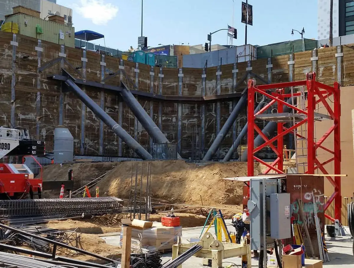
Tiebacks extend behind a shoring wall. Rakers brace it from inside the excavation. That difference affects the space available to dig, move equipment, and build the new foundations.
For an owner reading shoring drawings, the component names help explain how the excavation will be supported and where construction may be constrained. Cefali's work at Intuit Dome, The Grand, and other Los Angeles projects shows how those parts fit together.
Soldier piles: the wall's vertical supports
Soldier piles are vertical structural members installed along the excavation perimeter. Lagging or another facing system supports the ground between them as excavation proceeds. Depending on depth and loading, the piles may work in cantilever or receive additional support from tiebacks, rakers, cross-lot braces, or other systems.
At 1201 S. Hope, soldier pile shoring supported a five-level, 55-foot garage excavation. Three rows of tiebacks were coordinated around the garage geometry and nearby Metro light rail.
Pile size, spacing, embedment, and support are designed for the individual excavation. A pile line on a concept drawing leaves those details to be established.
Lagging: support between the piles
Lagging spans between soldier piles and is installed progressively as excavation exposes the soil. Its design and installation depend on the ground conditions, pile spacing, excavation sequence, and project requirements.
A drawing labeled “soldier pile and lagging” describes the wall's vertical elements and face. The tiebacks or internal braces needed to support a deep wall are additional parts of the system.
Tiebacks: anchors behind the wall
A tieback is drilled from the shoring wall into the ground behind it. This leaves more working space inside the excavation, but the anchor needs a clear path and available ground outside the cut. Property rights, utilities, neighboring foundations, tunnels, and other buried structures can limit its angle, length, and position.
At The Grand, short anchors were used near the active 2nd Street Tunnel. At Columbia Square, deep utilities required steep anchors and longer spans in portions of the excavation.
Where anchors cannot extend behind the wall, the support may need to move inside the excavation. The property-line shoring guide describes the alternatives and the space they require.
Walers: horizontal members along the wall
A waler distributes wall loads to anchors, braces, or other support points. It can transfer loads along the wall where support cannot connect directly at every pile.
At The Grand, an existing retaining wall blocked tieback drilling at some pile locations. Cefali used a multi-row waler system to transfer loads to locations where anchors could be installed.
Walers can also be part of a modification during construction. At 6th & Bixel, additional walers and tiebacks were added when the excavation had to go deeper than planned.
Rakers: inclined braces inside the excavation
A raker is an inclined compression brace. It can avoid some property and underground conflicts that prevent tiebacks, while taking up space inside the excavation. The base of the brace needs support too.
At G-8, a deep neighboring basement prevented a conventional tieback layout along part of the excavation. Rakers supported the wall, and the raker pad itself had to be restrained as excavation advanced near the P4 wall.
At Wilshire Grand, preloaded rakers were used at and below the level where nearby Metro tunnels prevented the lowest tieback support. Raker locations and their supports affect both the excavation sequence and the room available for permanent construction.
Cross-lot bracing: supports spanning the excavation
Cross-lot braces are compression members spanning between opposing shoring walls or support points. They can provide support where tiebacks are unavailable, but their height and position must fit around digging equipment, truck movement, foundations, and slabs.
At Intuit Dome, tieback agreements could not be secured for the entrance tunnel. Cross-lot braces were positioned above truck traffic so the construction route could remain usable.
The internal bracing guide explains how these supports affect access and construction.
Corner bracing: support across a corner
A corner brace transfers loads across a corner or toward another location where support is available. It often works with walers and other wall elements where the geometry does not suit a repeating tieback layout.
Cefali projects including Columbia Square, TEN50, and the West Hollywood Edition used corner bracing where property, utility, or site geometry affected the tieback arrangement. Each detail depended on the wall geometry and the rest of the support system.
Underpinning: support for an existing foundation
Shoring holds back ground. Underpinning supports an existing foundation or structural element when excavation or new construction affects its load path.
At 755 Fig, an existing vault required underpinning within a deep, constrained excavation that also used internal bracing and other temporary support.
A neighboring building does not automatically require underpinning. Its foundation and the proposed excavation need to be evaluated together to determine what support is needed.
Soil nails: reinforcement behind an excavated face
Soil nails reinforce the ground behind a wall, typically installed in stages as excavation progresses from the top down. They need enough available ground behind the face for the required nail geometry.
At Vista Monterey in Corona, Cefali used soil nail walls where easements were available. Soldier pile walls served the areas where property-line conditions prevented nail installation, giving the development different retaining systems along its walls.
Surcharge: loads near the excavation
A surcharge is a load near the excavation that affects the forces on the shoring. Nearby buildings, traffic, cranes, stored materials, and temporary platforms may all contribute, depending on their position and the design.
At 755 Fig, the narrow site had substantial adjacent-building surcharge conditions. At Intuit Dome, the temporary shoring design accounted for major construction equipment, including cranes and concrete pumps. The engineer needs those temporary loads and their locations as well as the information about surrounding buildings.
Instrumentation and monitoring: measuring performance during construction
Instrumentation measures movement or other project-specific performance indicators while construction proceeds. At Wilshire Grand Center, the tiebacks, rakers, soldier piles, and nearby tunnels were instrumented as part of the deep excavation. At TEN50, monitoring was used during pile installation beside an existing brick building.
Those measurements provide information to the responsible project team. The structural support itself still comes from the designed shoring system.
Discuss the shoring on your drawings
For a Los Angeles excavation, send Cefali & Associates the current plans, available geotechnical information, and known site constraints. Describe the part of the work you need help with, such as braces occupying a construction route, an anchor near a neighboring structure, or a change to the excavation depth. You can begin that conversation without choosing the individual shoring components yourself.