
A utility can occupy the same ground as a proposed shoring pile or tieback. Its depth matters as much as its route: an anchor that clears it in plan may still cross it below ground. Vaults, duct banks, and relocation work can also take up space needed for drilling equipment and excavation access.
At Columbia Square in Hollywood, deep utilities led to steep anchors and longer spans around a 60-foot excavation. At Hollywood Burbank Airport, Cefali coordinated the shoring with numerous new utility routes. Both existing and proposed underground work can change how the wall is supported.
Columbia Square: deep utilities changed the anchors
The Columbia Square redevelopment reached about 60 feet below the former CBS property. Narrow streets and deep utilities constrained the shoring.
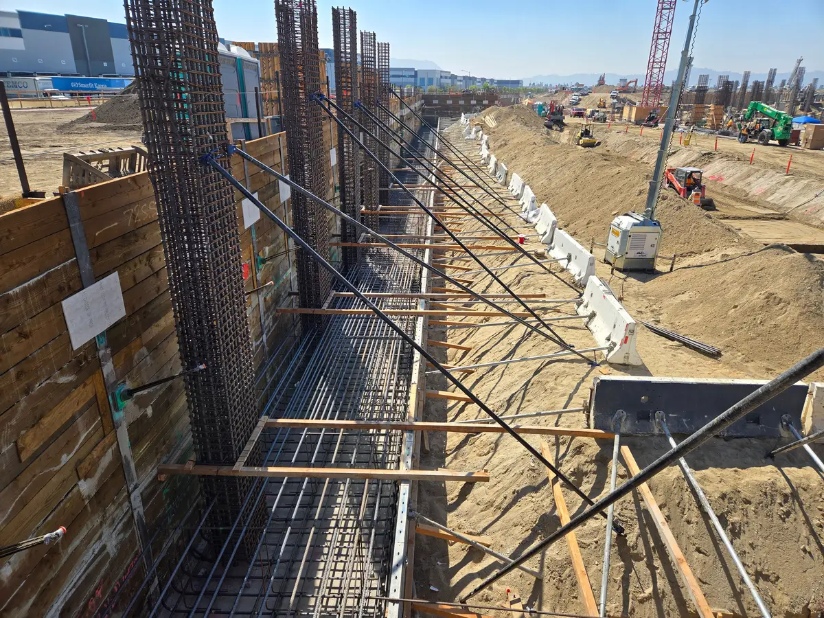
Steep anchors and longer spans were used to avoid conflicts, with up to five rows of tiebacks in some areas. The constraints affected anchor angle and load transfer along the wall, beyond the location of any single utility crossing.
A tieback extends behind the wall along a drilling path and bonded length. Utilities and other underground structures can limit its angle, elevation, and length. Their actual geometry is needed before the engineer can establish an anchor arrangement for the site.
The Grand: a tunnel and retaining wall restricted tieback locations
At The Grand in Downtown Los Angeles, underground conditions included tunnels, existing retaining walls, and dipping bedrock. Along 2nd Street, Cefali used short anchors to stay clear of the active 1920s 2nd Street Tunnel.
Along another side, an existing retaining wall prevented tieback drilling at some piles. A multi-row waler system transferred loads to positions where anchors could be installed.
That type of load transfer allows the wall design to respond to local restrictions. Its suitability depends on the support demands and the ground available for anchors, so the obstruction needs to be understood in relation to the surrounding wall.
New utilities can cross proposed or installed shoring
At the Hollywood Burbank Airport replacement terminal parking structure, the below-grade work was coordinated with large foundations, proposed grades, retaining walls, and many new utilities.
Cefali modeled the shoring in Revit and coordinated tieback clashes with utility trade partners in Navisworks. The review included proposed utility work, alongside the existing site conditions.
A later change to a civil, electrical, plumbing, or other utility route can affect proposed or installed shoring. The revised route needs to be checked against the pile line, anchor paths, bracing, foundations, and excavation stages it passes through.
Utilities can obstruct drilling even where they miss the anchors
A line, vault, or duct bank may occupy a soldier pile position or limit the space where the drill rig can work. A temporary relocation can also change when an area becomes available for excavation or support installation.
At Century Plaza, deep street utilities had to be considered alongside existing structures, future Metro work, and the redevelopment's excavation and foundations.
The temporary excavation shoring design needs that broader site information. Moving an anchor may solve one clash while leaving a pile inaccessible or placing a brace in the way of foundation construction.
A model cannot confirm a utility's location
A shared view of the excavation, piles, anchor zones, utility corridors, pits, vaults, and foundations makes their relationships visible. The model or drawing also needs to distinguish surveyed or investigated locations from preliminary records.
Where a utility position remains uncertain, that uncertainty belongs in the design information. Record research, survey, potholing or other required verification, utility relocation design, and utility-owner coordination sit with the parties appointed for that work. The shoring engineer uses the resulting information to design around the confirmed constraints.
Current drawing and model revisions matter because a moved utility or anchor can affect another team's work. The agreed geometry needs to carry through to the drawings used for installation, including changes made after a clash is resolved.
Have a utility conflict near your excavation?
Contact Cefali & Associates with the excavation and foundation drawings, existing and proposed utility information, survey, and geotechnical report. A marked section or current coordination model showing the conflict is especially helpful. Include available verification results, access restrictions, and the construction stage, and identify any utility location that remains uncertain.
That gives the engineer the geometry needed to assess the affected pile, anchor, or bracing arrangement.